In this post, I modified the data-path and RAM to be parameterized so they can handle LED Matrices up to sizes of 64×32. I also created a controller that utilizes the write functions in the data-path in order to change what is imaged on the LED matrix. The controller utilizes a UART receive module running at 1,000,000 baud to receive a data stream from a computer and write the data stream to the RAM.
Final Setup
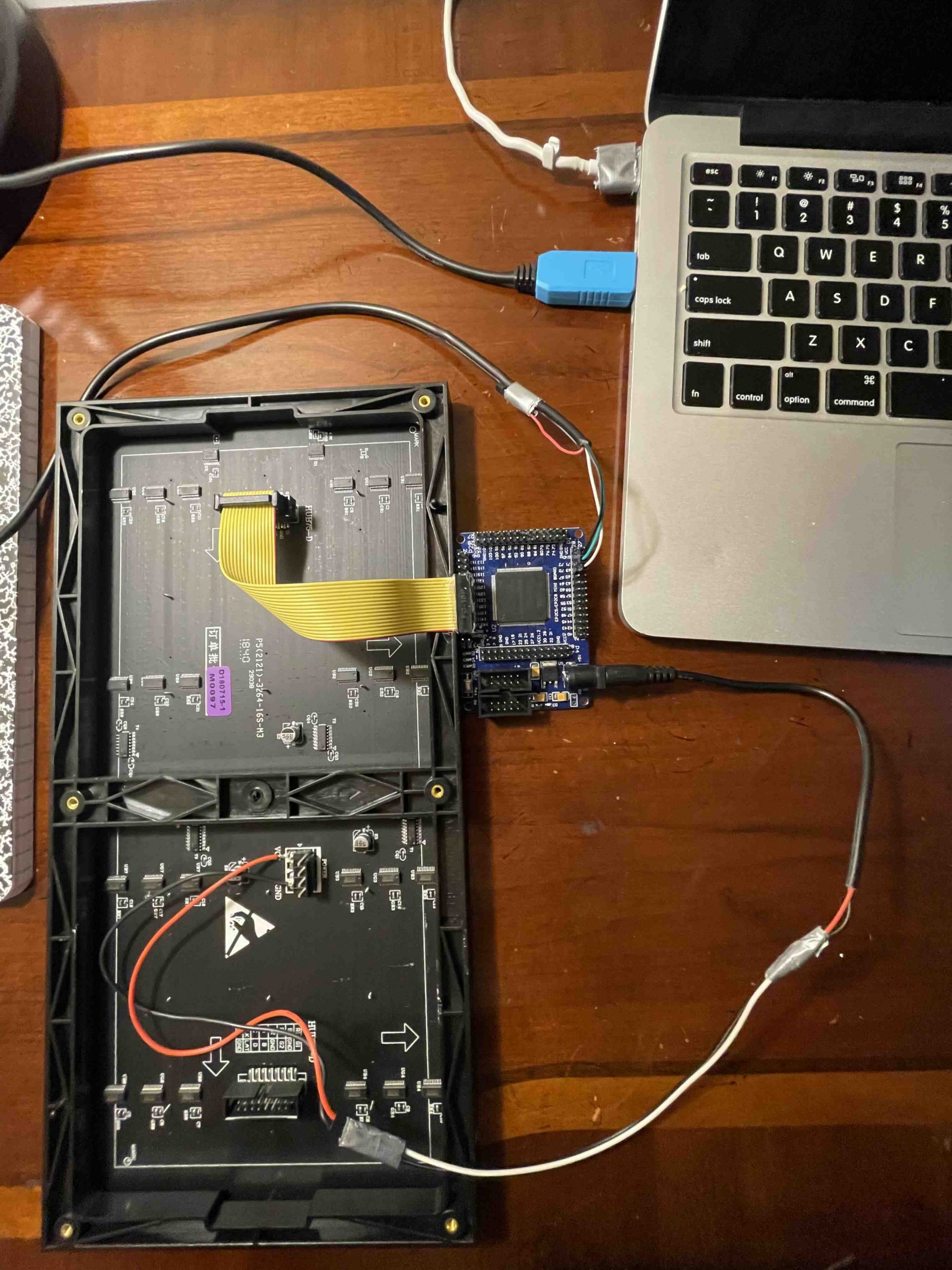
In my final setup, I will have my FPGA board connected to the LED matrix via an 8×2 pin female-female connector. The board will also be connected to a computer via a serial cable. I will use the pyserial module to use python the interface with the FPGA. This way I can use many pre-existing libraries to generate interesting things on the LED Matrix (patterns, text, etc).
Here are the materials used in the final setup:
- EP2C5T144 FPGA board
- USB Blaster (upload configuration to FPGA)
- Adafruit LED Matrix
- Adafruit Serial Cable
- 8×2 female ribbon cable
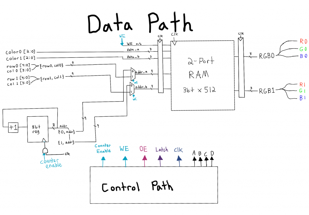
Modifications to datapath
In order to increase the flexibility of the project, I made the data-path module parameterized in terms of the number of columns and rows of the LED Matrix to be driven. The size of the RAM was also increased (the size of RAM should be increased to accommodate how many LED matrices you would like to chain together).
module led_matrix_data_path #(parameter R=6,parameter C=5)(
	input CLK,
	input RESET,
	input CE,
	input WE,
	input [R-1:0] row0,
	input [C-1:0] col0,
	input [2:0] color0,
	input [R-1:0] row1,
	input [C-1:0] col1,
	input [2:0] color1,
	output [2:0] RGB0,
	output [2:0] RGB1
	);

	reg [R+C-2:0] addr;
	always @(posedge CLK, posedge RESET) begin
		if(RESET) begin
			addr <= 0;
		end
		else if(CE) begin
			addr <= addr + 8'b1;
		end
		else begin
			addr <= addr;
		end
	end


	two_port_ram_64 color_matrix(
		.address_a((WE) ? {col0,row0} : {1'b0, addr}),
		.address_b((WE) ? {col1,row1} : {1'b1, addr}),
		.clock(CLK),
		.data_a(color0),
		.data_b(color1),
		.wren_a(WE),
		.wren_b(1'b0),
		.q_a(RGB0),
		.q_b(RGB1)
	);
endmodule
//////////////////////////////////////////////////////////////////////
// File Downloaded from http://www.nandland.com
//////////////////////////////////////////////////////////////////////
// This file contains the UART Receiver. This receiver is able to
// receive 8 bits of serial data, one start bit, one stop bit,
// and no parity bit. When receive is complete o_rx_dv will be
// driven high for one clock cycle.
//
// Set Parameter CLKS_PER_BIT as follows:
// CLKS_PER_BIT = (Frequency of i_Clock)/(Frequency of UART)
// Example: 10 MHz Clock, 115200 baud UART
// (10000000)/(115200) = 87
module uart_rx
#(parameter CLKS_PER_BIT)
(
input i_Clock,
input i_Rx_Serial,
output o_Rx_DV,
output [7:0] o_Rx_Byte
);
/////
///... more code
/////
endmoduleUART receiver
For the UART receiver module, I utilized a Verilog file from nandland.com. I parameterized their file according to their instructions taking my clock rate (25MHz) and dividing by the baud rate (1,000,000) to get the “CLKS_PER_BIT” parameter. This parameter is used when the uart_rx module is instantiated in the LED Matrix controller.
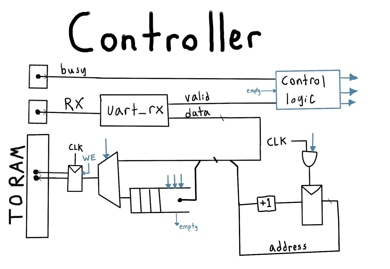
LED Matrix Controller
The purpose of the LED Matrix controller is to take the stream of data coming from serial and to write it to the RAM. The serial data stream consists of solely color data (one byte = color for one pixel). The data is written incrementally to the RAM (i.e. The first byte received appears at pixel (0,0) the next at (0,1) and so on).
In order to compensate for the periods when the RAM is being read (and hence busy) data that is received during these periods is stored into a hardware FIFO queue. When the RAM is no longer busy and data isn’t currently being received, then the FIFO is read from, and the data is written to the RAM.
The controller also has a control signal “0xff” that will cause the display to reset its internal address register and purge the FIFO. This control signal can be used every time a new frame is sent via serial to ensure new data is received and written correctly.
module led_matrix_controller #(parameter R=6,parameter C=5)(
	input RESET,
	input CLK,
	input busy,
	input RX,
	output reg WE,
	output reg [R-1:0] row0,
	output reg [C-1:0] col0,
	output reg [2:0] color0,
	output reg [R-1:0] row1,
	output reg [C-1:0] col1,
	output reg [2:0] color1
);

wire valid;
wire [7:0] rx_data;
uart_rx #(.CLKS_PER_BIT(25)) serial
(
   .i_Clock(CLK),
   .i_Rx_Serial(RX),
   .o_Rx_DV(valid),
   .o_Rx_Byte(rx_data)
);

wire [15:0] fifo_in_data;
wire [15:0]fifo_out_data;
wire fifo_clr;
wire fifo_empty;
wire rdreq;
wire wrreq;

busy_data_fifo busy_data(
	.clock(CLK),
	.data(fifo_in_data),
	.rdreq(rdreq),
	.sclr(fifo_clr),
	.wrreq(wrreq),
	.empty(fifo_empty),
	.full(),
	.q(fifo_out_data),
	.usedw()
);

assign wrreq = valid && (rx_data != 8'hff) && busy;
assign fifo_in_data = {addr,rx_data[2:0]};
assign rdreq = ~busy && ~valid && ~fifo_empty;
//If we receive the control signal, purge the fifo
assign fifo_clr = valid && (rx_data == 8'hff);


reg [R+C-1:0] addr;
reg write_ram;
reg prev_busy;
reg prev_valid;
always @(posedge CLK) begin
   prev_busy <= busy;
	prev_valid <= valid;
	//Write RAM if not busy, the data is valid, and not ff signal
	if((~busy) && (valid != prev_valid) && valid && (rx_data != 8'hff)) begin
		WE <= 1;
		row0 <= addr[R-1:0];
		col0 <= addr[R+C-1:R];
		color0 <= rx_data[2:0];
		addr <= addr + 1;
	end
	//If we are busy, we should store the data in FIFO to use latter
	else if(valid && (rx_data != 8'hff)) begin
		addr <= addr + 1;
	end
	//If the ff control signal was received, reset the address to zero
	else if(valid && (rx_data == 8'hff)) begin
		addr <= 0;
	end
	//If we aren't busy/not receiving data, write FIFO data to RAM
	else if(~busy && !valid && !fifo_empty) begin
		WE <= 1;
		row0 <= fifo_out_data[R+2:3];
		col0 <= fifo_out_data[R+C+2:R+3];
		color0 <= fifo_out_data[2:0];
	end
	else begin
		WE <= 0;
 	end
end

endmodule
The Result
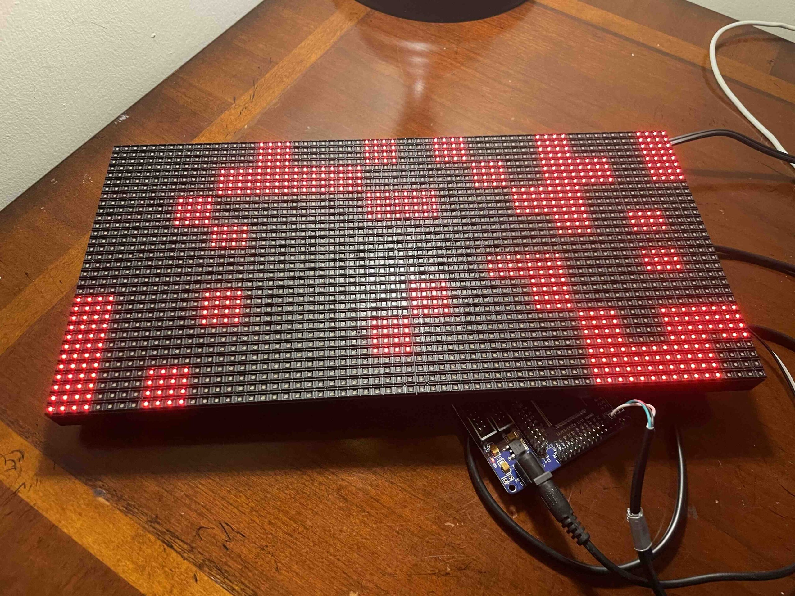
By running a simple python script I can make a cool randomized pattern flash on the screen.
import serial
import random
import time
import sys

ser = serial.Serial('/dev/ttyUSB0', 1000000, timeout = 0)
while True:
    rand_colors = []
    w, h = 32, 64;
    rand_blocks = [[0 for x in range(w)] for y in range(h)]
    for r in range(0,int(h/4)):
        for c in range(0,int(w/4)):
            r_val = random.randint(0,3)
            if r_val == 0:
                r_val = int(sys.argv[1])
            else:
                r_val = 0
            for off_r in range(0,4):
                for off_c in range(0,4):
                    rand_blocks[(r*4)+off_r][(c*4)+off_c] = r_val
    for i in range(0, w):
        for j in range(0, h):
            rand_colors.append(rand_blocks[j][i])

    rand_colors.insert(0, 255)
    byte_vals = bytearray(rand_colors)
    ser.write(byte_vals)
    time.sleep(0.01)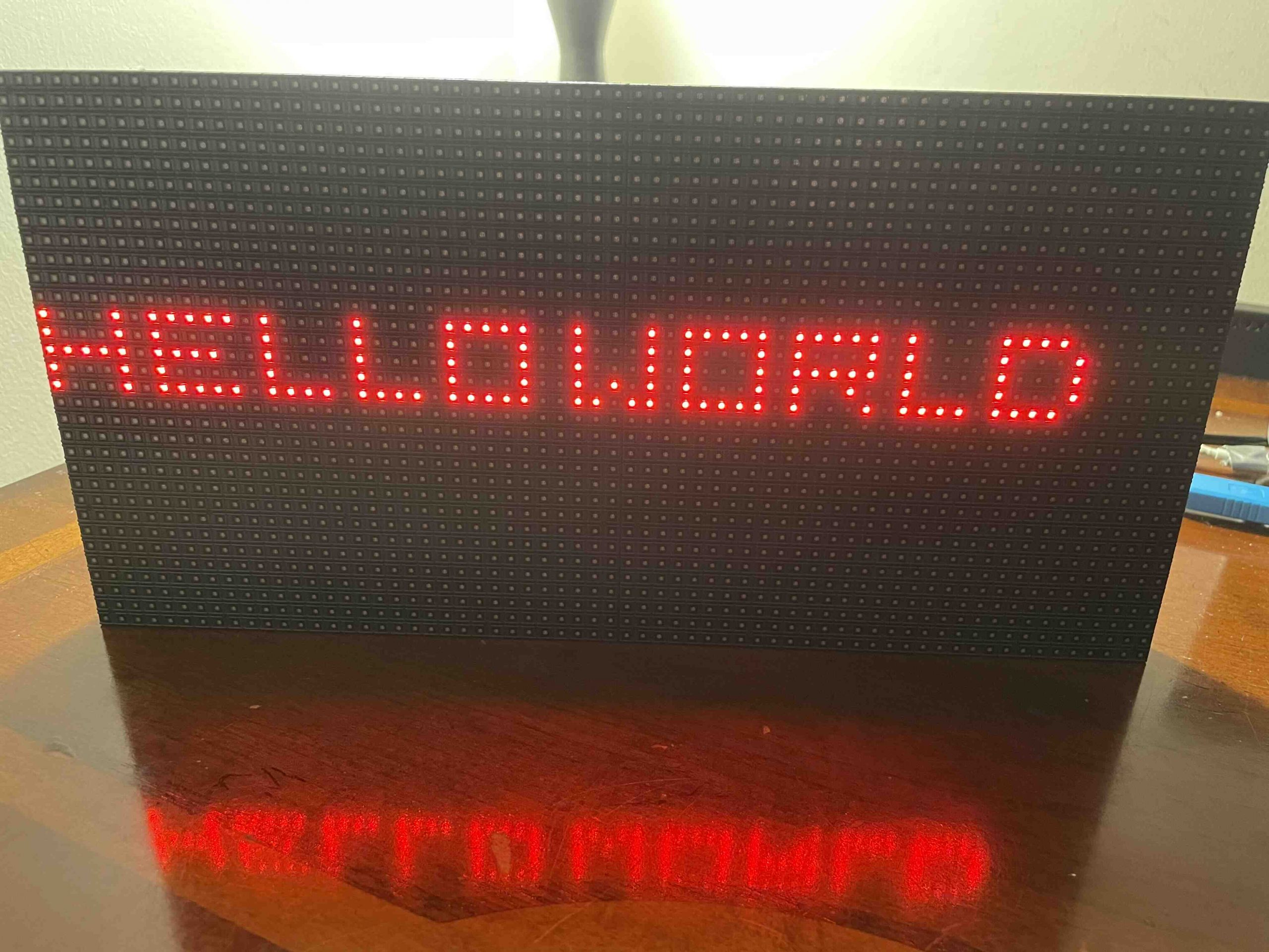
Leveraging other python libraries such as PIL and numpy, I can make the LED matrix display text as well.